Cylindrical Lapping Using Helilaps - Technical Article
Introduction To Cylindrical Lapping
Cylindrical Lapping is a two motion (rotation and reciprocation), low pressure, abrasive machining process which utilises a lapping tool along with an abrasive in a compound form. The lapping process results in stock removal ranging from a few Microns to several Tenths of a millimetre. Any desired surface finish can be achieved.
The following imperfections in cylindrical geometry can be corrected with helical laps:
- Correction of I.D. or O.D.
- Correction of out of round conditions
- Correction of bell-mouthed bores
- Correction of barrel-shaped bores
- Improvement in straightness of I.D. and O.D.
In addition to geometrical improvements, lapping can also provide:
- Improvement and refinement of surface finish quality
- Close tolerance accuracy at minimal cost compared to other finishing methods.
Cylindrical geometries that have been achieved with helical laps:
- 0.00014mm. roundness
- 0.00028mm. straightness
- Surface finish better than 0.025 Ra
Helical Laps are extremely versatile. They can be used on any machine with rotating spindle capacity, such as a drill, lathe or honing machine. Helical Laps can be used on virtually any material. Cast Iron, tool steel, carbide, stainless steel and ceramics are a few.
Internal Helical Laps are manufactured with radial grooves or without radial grooves. Radial grooves are advantageous in applications requiring stock removal greater than 0.01mm. Helical Laps without radial grooves are recommended for applications where the bore has interruptions or cross-holes. Expansion of internal Helical Laps is achieved by moving the lap (manufactured with tapered I.D) up an arbor which has a mating tapered O.D.
External Helical laps can be contracted by tightening an adjusting screw on the external lap holder. External laps are manufactured with either a straight or helical slot. Helical slots are most beneficial when lapping a shaft with a keyway. External laps should be shorter than the length of the O.D. being lapped, but long enough to span recesses or interruptions.
General Guidelines For Cylindrical Hole Lapping
These guidelines are intended to serve as an introduction to lapping
Lap Length:
For most applications using a lap slightly longer than the bore length will be sufficient. Using the following rule will allow you to obtain the correct lap length:
LAP LENGTH = BORE LENGTH PLUS 30% OF THE BORE LENGTH
Lap Fit:
The fit between the lap and the part being lapped should be such that the part can be stopped from rotating with some effort by a firm grasp of the hand. The fit should be monitored at the beginning of each lapping operation and adjusted accordingly.
Lapping Compounds And Abrasives:
Please contact KEMET Int. Ltd for a recommendation regarding your particular lapping application. We offer a full range of lapping compounds and abrasives. The most popular being kemet diamond compound and sabre aluminium oxide compound.
Spindle Speed:
100 to 300 RPM is acceptable for most applications.
Lap Expansion:
When the fit between the lap and the workpiece does not meet the criteria previously established, an adjustment must be made. Make this adjustment by gently tapping the lap up the arbor taper with the use of a lap expander and a mallet until the appropriate fit is once again achieved. Checking the fit after each successive tapping is necessary to ensure that over expansion of the lap does not occur. If this does occur, it is recommended that a lap puller be used to bring the lap down to the desired size.
Dressing The Lap
For more difficult applications where dimensions of straightness and/or roundness less than 0.001mm are called for, it is recommended that an external lap be used to “dress” (lap) the outer diameter of the internal lap. The operation will remove any “high spots” on the lap. Doing so will ensure a higher degree of dimensional stability.
Correcting Common Types Of Geometrical Flaws
The illustrations below define these commonly encountered geometric shapes:
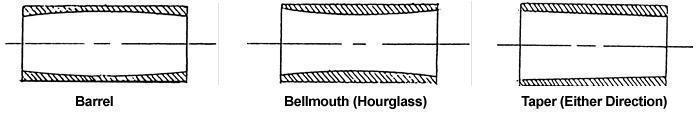
Barrel Effect
This characteristic shape is most likely the effect of a stroke length which is to long. This will cause the generation of a “high spot” on the central area of the lap. It is also possible that the fit between the lap and work piece is to loose.
Adjust the stroke. Dress the lap and adjust the fit as described in the “Lap Expansion” section. Ensure that the lapping abrasive is evenly distributed on the lap. Continue monitoring this until lapping is complete. Remove excess abrasive as required.
Bellmouth
This condition is generally caused by too short a stroke length and inherently a build-up of abrasive on the ends of the lap. This causes the lap to wear excessively in the centre.
Correct the stroke length. Dress the lap to ensure straightness and roundness. Assure that no abrasive build-up appears on the ends of the lap and that the lap is uniformly covered with abrasive. The use of a clean cloth or paper towel is advised.
Taper (Either Direction)
Lap the component on the half of the bore with the smaller end of the taper until a bellmouth shape is achieved. Once this is done refer to the section above.
Blind Hole Lapping Technique
A “Blind Hole” can be defined by the illustration below:
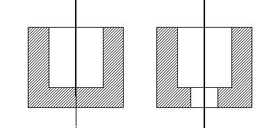
For successful lapping of such a hole, it is required that these modifications be made;
- Remove the undercut (laps under 9/64” have no undercut on the End of the lap with the small inner diameter
- Remove the protruding portion of the arbor.
- Relieve the lap diameter.
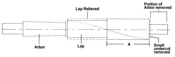
“A” = less than 50% of the bore length unless you get uneven wear on the lap and an error in the bore being lapped

Blind bore lapping using modified lap and arbor
Counterbore:
If the diameter of the through hole is large enough to accommodate the outer diameter of the arbor then no arbor modification is required.
Alternative:
A series of arbors with incremental increases in small-end diameters can be made to suit your application. This is desirable when a higher volume of pieces are to be lapped. This replaces an arbor-grinding modification.
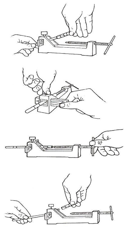
Removing helilaps from their arbors
It is advisable to retract the lap after use. As the lap is made of high-grade cast iron, this will allow it to “relax” which increases the life of the lap itself.
It is recommended that the specially-designed retraction tool is used, as shown in Fig. 3. This will prevent any malformation of the arbor.
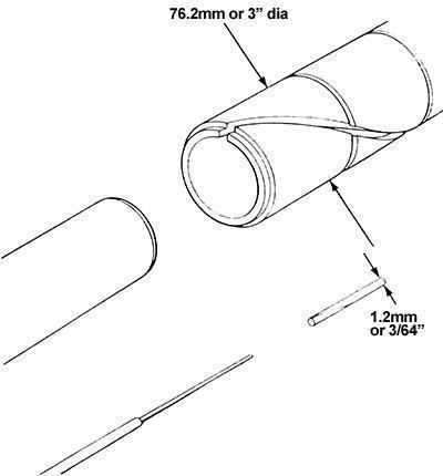
Helilap Design

Spirally slotted lap with uniform lines of contact
The HELILAP, made of a good quality, close-grained, lapping iron has a tapered bore to enable it to slide on a high-tensile, hardened and ground steel arbor. When the lap is driven up the arbor, expansion occurs, and by utilisation of uniform points of contact around the circle, the roundness of bores and diameters can be held to extremely fine limits. Also, because the points of contact extend on the circle through the length of the lap, parallelism can be guaranteed. The lap will contract on being pulled down the slope of the arbor but this contraction is limited and care should be taken in selecting the correct lap size.
Size comparison of small and large HELILAPS
External lapping
External lapping employs some of the same “rules of thumb” as internal lapping. However, there are fundamental differences.
The length of the lap should be less than the length of the workpiece. A shorter length lap is generally best when a higher degree of sensitivity is required by the operator. KEMET Int. Ltd would be pleased to recommend a particular length lap for your application.
When a shaft has two lands or any other interruptions, ensure the lap is long enough to span at least two lands. The illustration below may help to clarify.
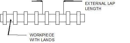
The fit between the lap and work piece is critical. The fit should be such that the lap can be stopped from rotating with some effort by a firm grasp of the hand (abrasive already applied).
When dressing an internal lap, primarily stroke the “high spots”. Continue dressing the lap until a uniform resistance is felt throughout the entire surface. When lapping a work piece the stroke should completely traverse the piece. The lap should, at the end of the stroke, slightly overlap the ends of the work piece. Allowing the piece to exit the bore of the external lap will cause rounding of edges.