Surface Roughness Explained: Ra vs Rz vs Rq
When a component's performance depends on how it seals, slides, bonds, or reflects light, surface roughness is often the single most important spec on the drawing. Yet the three letters used to describe it — Ra, Rz, and Rq — are frequently confused, misquoted, or used interchangeably when they shouldn't be.
This article breaks down what each parameter actually measures, how they're calculated, when to specify one over another, and how they relate to the surface finishes achievable through lapping and polishing.
What is surface roughness?
Every machined, ground, lapped, or polished surface — no matter how smooth it looks to the eye — is made up of microscopic peaks and valleys. Surface roughness quantifies these irregularities relative to an idealised, perfectly flat reference (the "mean line" or "mean plane").
Roughness is one part of the broader concept of surface texture, which also includes waviness (longer-wavelength deviations, often caused by machine vibration or deflection) and lay (the direction of the dominant surface pattern). Ra, Rz, and Rq specifically describe the height variation of the roughness profile — they don't tell you anything about the pattern's direction or spacing.
Ra — Arithmetic Average Roughness
Ra (also called AA or CLA — Centre Line Average) is by far the most commonly specified roughness parameter, and for good reason: it's simple, robust, and repeatable.
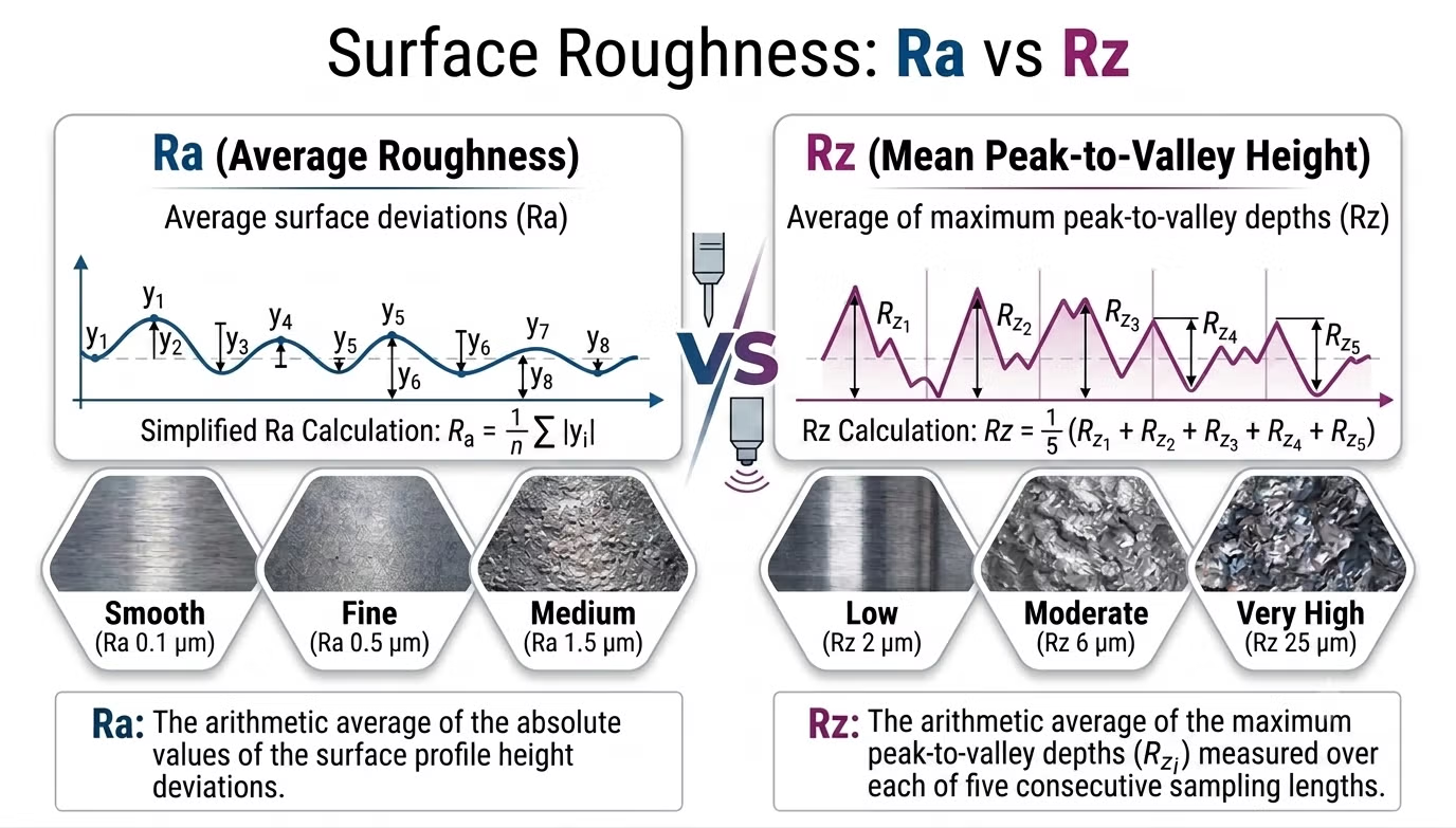
Ra is the arithmetic mean of the absolute values of the profile height deviations from the mean line, measured over a defined sampling length.
In plain terms: take every point on the surface profile, measure how far it is from the mean line (ignoring whether it's a peak or a valley), and average all those distances.
Why it's popular:
- A single number that's easy to specify, measure, and compare across suppliers
- Relatively insensitive to occasional large scratches or isolated defects, since it averages the whole profile
- Widely supported by every profilometer and most drawing standards (ISO 21920, ASME B46.1)
Its main limitation: because Ra averages everything out, two surfaces with very different profiles — one with lots of small, even texture and another with a few deep, isolated scratches — can report the same Ra value despite behaving completely differently in service (e.g. for sealing or fatigue life).
Rz — Average Maximum Height
Rz looks at extremes rather than averages, which makes it a useful companion to Ra rather than a replacement for it.
Rz is calculated by dividing the sampling length into several equal sections, finding the maximum peak-to-valley height within each section, and then averaging those maximum values.
Important caveat: there are two different definitions of Rz in use internationally, and mixing them up is a common source of drawing errors:
- ISO Rz (most common today): the average of the five largest single peak-to-valley heights across five sampling lengths
- DIN Rz (older German standard): similar in concept but with slightly different sectioning rules
- Rz (JIS, older Japanese ten-point standard): averages the five highest peaks and five lowest valleys separately
If a supplier or customer quotes "Rz" without specifying the standard, it's always worth clarifying which definition is intended — the values are not directly interchangeable.
Why it matters: Rz is far more sensitive to isolated peaks and deep scratches than Ra. Two surfaces can have identical Ra values but very different Rz values if one has occasional deep gouges. For sealing surfaces, fatigue-critical components, and anywhere a single deep scratch could cause leakage or crack initiation, Rz is often the more meaningful specification.
Rq (RMS) — Root Mean Square Roughness
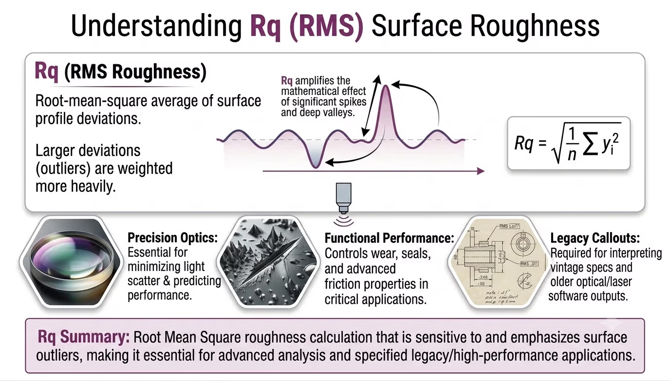
Rq, sometimes labelled RMS on older drawings and optical/laser measurement reports, is the root-mean-square average of the profile height deviations.
Where Ra simply averages the absolute deviations, Rq squares each deviation before averaging, then takes the square root of the result. This weighting means larger deviations have a proportionally bigger effect on the final number than they do in an Ra calculation.
Key relationship: for most real-world engineering surfaces, Rq is numerically slightly higher than Ra — typically by a factor of around 1.11 to 1.3, depending on the shape of the surface profile. There's no fixed universal conversion factor between them, so Rq should always be measured directly rather than estimated from Ra.
Where Rq is used:
- Optics, photonics, and semiconductor wafer specifications, where RMS roughness correlates directly with light scatter and functional performance
- Legacy drawings and older optical measurement software, which often default to RMS/Rq rather than Ra
- Statistical and scientific surface analysis, where the RMS calculation has convenient mathematical properties
Ra vs Rz vs Rq: Side-by-Side Comparison
| Parameter | What it measures | Sensitivity to defects | Typical use case |
|---|---|---|---|
| Ra | Average of all height deviations from the mean line | Low — averages out isolated peaks/scratches | General engineering drawings, most common default spec |
| Rz | Average of the maximum peak-to-valley heights across sections | High — driven by the worst local defects | Sealing faces, fatigue-critical surfaces, leak-tight components |
| Rq (RMS) | Root-mean-square of height deviations | Moderate-high — squared weighting favours larger deviations | Optics, semiconductor, legacy/scientific specifications |
Which parameter should you specify?
There's no single "correct" answer — the right parameter depends on what the surface actually needs to do:
- General machined and lapped components: Ra is usually sufficient and is the industry default on most drawings
- Sealing surfaces (valves, mechanical seals, hydraulic components): specify Rz alongside Ra, since a single deep scratch can cause a leak path even when the average Ra looks acceptable
- Optical components, wafers, and photonics: Rq (RMS) is frequently the governing specification, as it correlates more directly with light scattering performance
- Fatigue-critical or safety-critical parts (aerospace, medical implants): Rz or maximum peak height (Rp) is often added as a secondary check, because crack initiation tends to start at the deepest surface defect rather than the average texture
Where possible, it's good practice to specify more than one parameter on critical drawings — for example Ra 0.05 µm max with Rz 0.3 µm max — so that both the average finish and the worst-case defect are controlled.
How lapping and polishing achieve these tolerances
Roughness values in the sub-micron range — the kind regularly required on sealing faces, optical components, and semiconductor substrates — are rarely achievable through machining alone. This is where lapping and polishing come in.
Lapping uses a controlled abrasive process between a workpiece and a reference plate to remove material extremely gradually and evenly, correcting both flatness and surface texture at the same time. Polishing follows to refine the surface further, often using progressively finer diamond slurries or colloidal suspensions.
Typical results achievable through diamond lapping and polishing processes include:
- Ra values as low as 0.007–0.025 µm on hardened metals, ceramics, and carbides
- Corresponding flatness tolerances down to 0.001 mm
- Mirror or near-mirror finishes on materials from stainless steel and titanium to sapphire and technical ceramics
Because lapping removes material uniformly across the whole surface rather than in a single directional pass (as grinding or turning does), it's particularly effective at controlling both Ra and Rz simultaneously — reducing the average texture while also eliminating the isolated deep scratches or tool marks that drive up Rz.
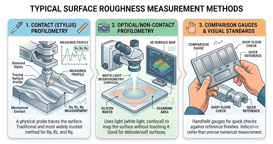
How surface roughness is measured
Roughness values are typically measured using:
- Contact (stylus) profilometry — a diamond-tipped stylus is dragged across the surface, physically tracing the profile. This is the traditional, most widely trusted method for Ra, Rz, and Rq measurement.
- Optical/non-contact profilometry — uses white light interferometry or confocal microscopy to map the surface without touching it, useful for delicate or soft surfaces.
- Comparison gauges and visual standards — used for quick shop-floor checks against a reference finish, though these are indicative rather than a precise numerical measurement.
Key takeaways
- Ra is the average roughness and the most commonly specified value — good for general comparison, less sensitive to isolated defects
- Rz captures the worst-case peak-to-valley height and is critical for sealing and fatigue-sensitive surfaces — always confirm which Rz standard (ISO/DIN/JIS) is being used
- Rq (RMS) weights larger deviations more heavily and is the standard in optics and semiconductor applications
- For critical components, specifying more than one parameter gives a fuller, more reliable picture of surface quality than any single value alone
- Achieving sub-micron Ra/Rz/Rq values consistently, on a wide range of materials, is exactly what precision lapping and polishing processes are designed to deliver
If you're specifying a surface finish and aren't sure which parameter — or which achievable tolerance — is right for your application, get in touch with Kemet's technical team to discuss your requirements.