How to Measure Flatness - Technical Article
There are a number of ways to measure the flatness of a surface. The most common method within the Flat Lapping sector is by using a Monochromatic Sodium light unit and an Optical Flat. This gives extremely precise measurements, more accurate than most CMM measurements, in an economical way.
What are light bands?
Light Bands were discovered by Isaac Newton who first studied them in 1717. They are an interference pattern created by the reflection of light between two surfaces.
When using a monochromatic light source it is possible to use the phenomenon to calculate the flatness of a component, but the surface of the component must be reflective in order for the light bands to appear. The light bands are made up of a bright and dark fringe. Combined, these correspond to the wavelength of the monochromatic light which in the case of a Sodium light source is equal to 589nm. When checking parts for flatness, it is only the dark bands that are counted, so as this is half the total fringe, each dark band equals 294nm or 0.00029mm.
Diamond lapping processes are ideal for producing reflective surfaces, which can be measured for flatness using this method directly after the lapping operation.
Flatness Calculator
Typical light band patterns which show flatness accuracy
| Surface geometry | 1 Light band 0.00029mm | 2 Light bands 0.00058mm | 3 Light bands 0.00087mm | 9 Light bands 0.00261mm | |
|---|---|---|---|---|---|
Convex or ConcaveSurface parallel to flatSymmetrical Pattern | 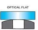 | 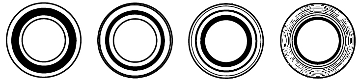 | |||
ConvexWith concave surface band will curve in opposite directionNon-Symmetrical Pattern | 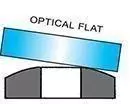 |  | |||
CylindricalConvex or ConcaveSymmetrical Pattern | 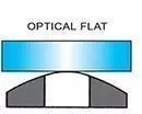 |  | |||
Saddle ShapedSymmetrical Pattern | 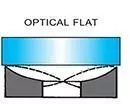 | 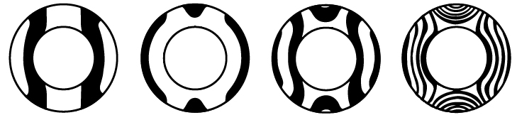 | |||
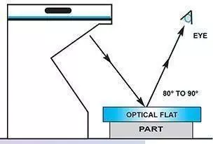
Measuring Flatness with Optical Flats
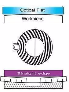
First clean the surfaces of the component and optical flat with a lens tissue or soft lint free cloth. Both faces must be absolutely clean. Place the optical flat carefully on top of the component. Do not slide it across. As the optical flat and component come together lines will appear through the flat. Manipulate it to obtain a line pattern, as illustrated. The lines are interference fringes or bands and are an indication of the level the component’s surface has risen or fallen in relation to the optical flat.
After obtaining the line pattern, you can start to interpret it to measure the surface of the component. The width of each fringe corresponds to the distance between the component and the optical flat at that point. In general, wider fringes indicate a larger distance, while narrower fringes indicate a smaller distance.
To calculate the amount of surface deviation, you can use a formula that takes into account the wavelength of the light, the distance between the fringes, and the refractive index of the material. With this information, you can determine the flatness of the component to a high degree of accuracy. Optical flats are widely used in the manufacturing and testing of precision components, such as optical lenses and semiconductor wafers. By using an optical flat to measure surface flatness, manufacturers can ensure that their products meet strict quality standards and perform optimally in their intended applications.
Light band reading Showing perfect flatness
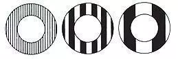
Lapping plate flatness
CONVEX
Ring pattern moves towards finger pressure. If workpiece is convex the lapping plate is concave.
Lapping plate concave
The control rings must be moved to the outside of the plate to correct this conditionCONCAVE
Ring pattern moves away from finger pressure. If workpiece is concave the lapping plate is convex.

Lapping plate convex
The control rings must be moved to the inside of the plate to correct this conditionThe straight parallel bands, and not the width of light band indicates the flatness.
Measuring Flatness vs Parallelism
While flatness and parallelism are related, they are not the same thing. Flatness measures the degree to which a single surface is level and smooth, while parallelism measures the degree to which two surfaces are aligned with each other. In other words, flatness is an individual property, while parallelism is a comparative property. Additionally, flatness is typically measured using a surface plate and a dial indicator, while parallelism is typically measured using a surface plate and a height gauge or dial indicator.
Flatness refers to the degree to which a surface is perfectly level and smooth. A flat surface has no high points or low points, and is completely even. Flatness is typically measured using a surface plate, which is a large, flat piece of granite or cast iron. A surface plate is used as a reference surface, against which the flatness of a part can be measured. To measure flatness, the part being measured is placed on the surface plate and a dial indicator is used to measure the distance between the part and the surface plate at various points. The readings are taken at different locations across the surface of the part to ensure that it is uniformly flat. The flatness of the surface is then calculated by comparing the readings taken at each point to determine the deviation from the perfect flatness.
Parallelism refers to the degree to which two surfaces are perfectly parallel to each other. In other words, parallelism measures how closely two surfaces are aligned with each other. Parallelism is also typically measured using a surface plate, along with a height gauge or dial indicator. To measure parallelism, two parts are placed on the surface plate, with one part resting on top of the other. The height gauge or dial indicator is then used to measure the distance between the two parts at various points along their surfaces. The readings are taken at multiple locations to ensure that the two surfaces are uniformly parallel. The parallelism of the surfaces is then calculated by comparing the readings taken at each point to determine the deviation from perfect parallelism.
Surface Finish Chart
Surfaces are produced by a variety of material removal processes. The total geometry which results can best be considered to be split-up into three components - roughness, waviness and form.
Basic parameters
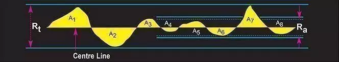
Parameters - The various parameters Ra, and Rt are illustrated. It may be seen that the centre line is that line which divides the areas such that: A1 + A3 + ............ A7 = A2 + A4 + ............ A8 The two most common surface finish measurements are Ra and Rt These are described as follows:
Ra is universally recognised as the most used international parameter of roughness. It is the arithmetic mean of the departures of the roughness profile from the mean line.
Rt is the maximum peak to valley height of the profile over the measured length. Measurements are usually quoted in microns. 1 Micron = Approx 40 Micro Inch
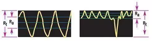
Examples of Ra and Rt
Typical statements of surface finish or texture on drawing:
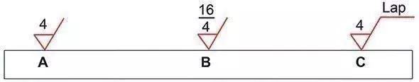
Symbol A How to specify maximum roughness value in Ra microns.
Symbol B How to specify maximum and minimum roughness values.
Symbol C How to specify maximum roughness and finishing process.
Kemet conversion tables
| Imperial to Metric | ||||
|---|---|---|---|---|
| Millimetres (mm) | Microns (μm) | Angstroms (Å) | ||
| 1 INCH (1.00”) | = | 25.4 | 25,400 | 254,000,000. |
| 1 THOUS. (0.001”) | = | 0.0254 | 25.4 | 254,000 |
| 1 MICRO INCH (μin) | = | 0.0000254 | 0.0254 | 254 |
| Metric to Imperial | ||||
| Inches | Thousandths | Micro-inches | ||
| 1 MILLIMETRE (mm) | = | 0.039 37 | 39.37 | 39,370 |
| 1 MICRON (μm) | = | 0.000 039 37 | 0.039 37 | 39.37 |
| 1 ANGSTROM (Å) | = | 0.000 000 003 937 | 0.000 003 937 | 0.003 937 |
Equipment for measuring flatness
Kemet Optical Flats
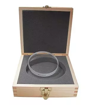
Produced from Quartz, Kemet Optical Flats are available in single and double sided, 1/4 light band or 1/10 light band accuracy. Standard sizes from 25mm up to 300mm diameter.
Kemet Monochromatic Light

Produces clear flatness readings when used with Kemet Optical Flats. The compact designed Light is easily transportable and uses a sodium long-life sodium light source. Supplied with a flatness reading interpretation chart.
Kemet Flatness Gauges
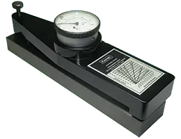
The Kemet Flatness Gauge is used to monitor a lapping plate’s flatness and to give an indication of the flatness the plate will produce on a given part size.