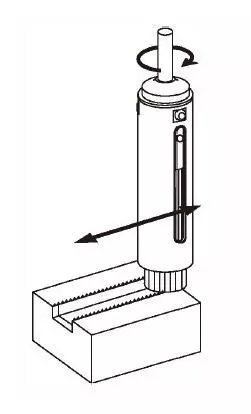
How to use Deburring Tool
Using Xebec deburring tools correctly can help to ensure consistent and high-quality results. These tools are designed to remove burrs and other imperfections with precision and speed, and using them correctly can help to avoid over-cutting or under-cutting the workpiece. This is especially important when working with complex geometries or delicate materials that require careful handling. By following the manufacturer's instructions and best practises, operators can achieve the desired surface finish and dimensional accuracy, which can improve product performance, reliability, and aesthetics.
Deburring tools operate at high speeds and generate significant heat, vibrations, and debris, which can pose a danger to operators if not handled properly. For instance, if the tool is not securely mounted or the workpiece is not properly supported, it can cause the tool to slip, break, or fly off, causing injury to the operator or others nearby. Similarly, if the operator does not wear appropriate personal protective equipment, such as safety glasses, gloves, and earplugs, they can be exposed to flying debris, noise, and dust, which can cause eye injuries, cuts, burns, and respiratory problems. By using Xebec deburring tools correctly, operators can minimise these risks and ensure a safe and healthy work environment.
These tools are designed to be durable and long-lasting, but they can wear out quickly if not used correctly or maintained properly. For instance, if the tool is subjected to excessive heat, pressure, or lateral forces, it can cause the abrasive material to wear out or break down, reducing its cutting ability and efficiency. Similarly, if the tool is not cleaned, lubricated, or stored correctly, it can lead to rust, corrosion, or contamination, which can affect its performance and longevity.
Below are guidelines for utilising specific Xebec deburring brushes
Usage tips for XEBEC Brush™ Surface
Recommended rotational speed and maximum rotational speed are different depending on Brush size. See the table below.
Initial processing conditions
| Product code | Rotational speed (min-1) | Depth of cut (mm) | Feed rate (mm/min) | Brush projection (mm) | ||||||
|---|---|---|---|---|---|---|---|---|---|---|
| Recommended | Maximum | Vertical burrs | Horizontal burrs | Cutter mark removal | Polishing | Burr root thickness 0.05mm | Burr root thickness 0.1mm | Cutter mark removal / polishing | ||
| A13-CB06M | 8000 | 10000 | 0.5 | 0.5 | 0.5 | 0.3-0.5 | 4000 | 2500 | 300 | 10 |
| A11-CB06M / A21-CB06M | 8000 | 10000 | 0.5 | 0.5 | 0.5 | 0.3-0.5 | 4000 | 2500 | 300 | 10 |
| A32-CB06M | 8000 | 10000 | 0.3 | 0.3 | 0.3 | 0.2-0.3 | 4000 | 2500 | 300 | 10 |
| A13-CB15M | 4800 | 6000 | 1 | 1 | 0.5 | 0.3-0.5 | 4000 | 2500 | 300 | 10 |
| A11-CB15M / A12-CB15M / A32-CB15M | 4800 | 6000 | 0.5 | 1 | 0.5 | 0.3-0.5 | 4000 | 2500 | 300 | 10 |
| A11-CB25M / A21-CB25M / A32-CB25M | 4000 | 5000 | 0.5 | 1 | 0.5 | 0.3-0.5 | 4000 | 2500 | 300 | 15 |
| A11-CB40M / A21-CB40M / A32-CB40M | 2400 | 3000 | 0.5 | 1 | 0.5 | 0.3-0.5 | 4000 | 2500 | 300 | 15 |
| A11-CB60M / A21-CB60M / A32-CB60M | 1600 | 2000 | 0.5 | 1 | 0.5 | 0.3-0.5 | 4000 | 2500 | 300 | 15 |
| A11-CB100M / A21-CB100M / A32-CB100M | 960 | 1200 | 0.5 | 1 | 0.5 | 0.3-0.5 | 4000 | 2500 | 300 | 15 |


Which Deburring Brush do I need?
Refer to the chart below and select brush colour based on the workpiece material, burr root thickness and target surface.
Which brush for Deburring?
| Workpiece material | Resin | Copper or Brass | ||
|---|---|---|---|---|
| Aluminium | ||||
| General Steel | ||||
| Stainless Steel | ||||
| Heat-resistant Steel | ||||
| Cast-iron | ||||
| Hard to cut material | ||||
| Thickness of burrs | Micro fine burrs | |||
| Burr root thickness ( < 0.1mm) | ||||
| Burr root thickness (0.1 - 0.2mm) | ||||
| Brush | A13 (pink) | A11 (red) | A21 (White) | A32 (Blue) |
Which brush for Cutter Mark removal?
| Workpiece material | Copper or Brass | |||
|---|---|---|---|---|
| Aluminium | ||||
| General Steel | ||||
| Stainless Steel | ||||
| Heat-resistant Steel | ||||
| Cast-iron | ||||
| Plastic and Hard to cut material | ||||
| Achievable Surface roughness | < Ra 0.1 µm | |||
| Ra 0.1 µm > | ||||
| Brush | A13 (pink) | A11 (red) | A21 (White) | A32 (Blue) |
Dry/Wet Machining
The tool can be used for both dry and wet (oil-based and water-soluble) machining. Wet machining may improve surface finish quality and tool life.
If burrs remain
- Increase rotational speed. Increase the rotational speed to the maximum. If burrs still remain, then decrease the feed rate.
| Brush diameter (mm) | Product code | Recommended rotational speed (min-1) | Maximum rotational speed (min-1) |
|---|---|---|---|
| 6 | A13-CB06M / A11-CB06M / A21-CB06M / A32-CB06M | 8000 | 10000 |
| 15 | A13-CB15M / A11-CB15M / A21-CB15M / A32-CB15M | 4800 | 6000 |
| 25 | A11-CB25M / A21-CB25M / A32-CB25M | 4000 | 5000 |
| 40 | A11-CB40M / A21-CB40M / A32-CB40M | 2400 | 3000 |
| 60 | A11-CB60M / A21-CB60M / A32-CB60M | 1600 | 2000 |
| lOO | All-CBlOOM / A21-CB100M / A32-CB100M | 960 | 1200 |
| 125 | A11-CB125M / A21-CB125M / A32-CB125M | BOO | 1000 |
| 165 | A11-CB165M / A21-CB165M / A32-CB165M | 600 | 750 |
| 200 | A11-CB200M / A21-CB200M / A32-CB200M | 480 | 600 |
- Check the rotation direction of the Brush. For horizontal burrs, up cut is recommended so that the brush tip pushes up the burrs.
- Change the Brush colour. Change the Brush with higher grinding power. The grinding power of the Brush: Blue> White> Red> Pink Make sure to select Brush colour based on the workpiece material and burr root thickness.
If the edge is too rounded
- Increase feed rate. To make sharp edge, increase the feed rate in 1000 mm/min increments within the range where burrs can be removed. Increasing the feed rate also helps reduce cycle time.
- Decrease rotational speed. Decrease the rotational speed in 10 to 20% increments within the range where burrs can be removed.
- Check the Brush colour. The grinding power of the Brush: Blue> White> Red> Pink Select Brush colour based on the workpiece material and burr root thickness.
To extend tool life
- Increase feed rate. Increase the feed rate in 1000 mm/min increments within the range where burrs can be removed.
- Decrease rotational speed. Decrease the rotational speed in 10 to 20% within the range where burrs can be removed.
If the surface becomes rough
Check the Brush colour. Change the Brush with higher edge quality. Edge quality of the Brush: Pink> Red> White> Blue Make sure to select Brush colour based on the workpiece material and target surface roughness.
REFERENCE DATA: SURFACE ROUGHNESS AFTER DEBURRING
| A11(Red) | A21(White) | A32(Blue) | |
|---|---|---|---|
| A5052 | Approx. Ra0.6µm, Rz5.0 µm | ||
| S50C | Approx. Ra0.2 µm, Rz1.6µm | ||
| SUS304 | Approx. Ra0.3µm, Rz2.4µm |
To improve surface roughness
- Check the Brush colour. Make sure to select appropriate Brush colour. Edge quality of the Brush : Pink > Red >White> Blue
- Wet machining. The tool can be used for both dry and wet (oil-based and water-soluble) machining. Wet machining may improve surface roughness and tool life.
- Increase the number of passes. When comparing in the same cycle time, increasing the number of passes makes bigger difference than decreasing feed rate.
Example
Rotational speed: 4000min-1
Depth of cut : 0.5mm
Feed rate: 600mm/min
The number of passes: 1
Rotational speed: 4000min-1
Depth of cut: 0.5mm
Feed rate: 1200mm/min
The number of passes: 2
REFERENCE DATA: TOOL LIFE
Material: Aluminium die-casting
Process details: Deburring after face milling process
Burr root thickness: 0.1 mm
Traveling distance: 1000mm/pcs
Tool: A11-CB25M
Rotational speed:4000min-1
Feed rate: 2400mm/min
Depth of cut: 1.0mm
Used length: 50mm out of 75mm
Tool life:
10km
10,000pcs (10km/1000mm)

Material: Carbon Steel S45C
Process details: Deburring after end milling process
Burr root thickness: 0.1mm
Traveling distance: 200mm/pcs
Tool: A21-CB25M
Rotational speed: 4000min-1
Feed rate: 2000mm/min
Depth of cut: 0.5mm
Used length: 50mm out of 75mm
Tool life: 3km
15,000pcs (3km/200mm)
* Tool life significantly varies depending on processing conditions, burr conditions (size and direction) and workpiece material. The above data is not guaranteed, please use as a guide.
Usage tips for XEBEC Brush™ Surface Extra-Large
Initial processing conditions
| Product code | Rotational Speed (min-1) | Depth of cut (mm) | Feed rate (mm/ min) | Brush projection (mm) | ||||||
|---|---|---|---|---|---|---|---|---|---|---|
| Recommended | Maximum | Vertical burrs | Horizontal burrs | Cutter mark removal | Polishing | Burr root thickness 0.05mm | Burr root thickness 0.1mm | Cutter mark removal/ Polishing | ||
| A11-CB125M / A21-CB125M / A32-CB125M | 800 | 1000 | 0.5 | 1 | 0.5 | 0.3-0.5 | 4000 | 2500 | 300 | 15 |
| A11-CB165M / A21-CB165M / A32-CB165M | 600 | 750 | 0.5 | 1 | 0.5 | 0.3-0 .5 | 4000 | 2500 | 300 | 15 |
| A11-CB200M / A21-CB200M / A32-CB200M | 480 | 600 | 0.5 | 1 | 0.5 | 0.3-0 .5 | 4000 | 2500 | 300 | 15 |
Please refer to above of XEBEC Brush Surface for an improvement method when it does not work.
Usage tips for XEBEC Brush™ Surface End Type
How to select
Grinding power differs depending on Brush colour. Refer to the chart and select Brush colour based on the workpiece material and burr root thickness.
| Workpiece material | Resin | Copper or Brass | ||
|---|---|---|---|---|
| Aluminium | ||||
| General Steel | ||||
| Stainless Steel | ||||
| Heat-resistant Steel | ||||
| Cast-iron | ||||
| Hard to cut material | ||||
| Thickness of burrs | Micro fine burrs | |||
| Burr root thickness (Up to 0.1mm) | ||||
| Target Surface roughness | Ra0.1 μm or better | |||
| Up to Ra0.1 μm | ||||
| Brush | A13 (pink) | A11 (red) | A21 (White) | A32 (Blue) |
Usage tips for XEBEC Brush™ Wheel Type
Initial processing conditions
| Product code | Cutting speed (m/min) | Rotational speed (min-1) | Feed per bundle (mm/bundle) | Depth of cut (mm) | Feed rate (mm/min) |
|---|---|---|---|---|---|
| W-All-50 | 250 | 1600 | 0.5 | 0.2 | 4800 |
| W-All-75 | 250 | 1000 | 0.5 | 0.2 | 3000 |
Processing Conditions Range
| Product code | Cutting speed (m/min) | Feed per bundle (mm/ bundle) | Depth of cut (mm) | Maximum rotational speed(min-1) |
|---|---|---|---|---|
| W -All -50 | 150-350 | 1.5or less | 0.5or less | 3000 |
| W -All -75 |
* As bristles are worn out, bristle length becomes shorter and increases stiffness, causing bristles to be broken. If bristles breakage occurs, decrease the depth of cut.
If burrs remain
- Increase the number of passes
- Decrease the feed per bundle in 10 to 20% increments
To extend tool life
Increase the feed per bundle in 10 to 20% increments
REFERENCE DATA: TOOL LIFE
Material: Carbon Steel S45C
Process details: Deburring after end milling
Burr root thickness: 0.1mm
Traveling distance: 120mm/pcs
Tool: W-A11-50
Cutting speed: 250m/min
(Spindle Speed: 1600min-1)
Feed per bundle: 0.7mm/bundle
(Feed rate: 7000mm/min)
Depth of cut: 0.2mm
Used length: 10mm out of 13.5mm
Tool life:
600m
5,000pcs (600m/120mm)

* Tool life significantly varies depending on processing conditions, burr conditions (size and direction) and workpiece material. The above data is not guaranteed. Please use as a guide.
Usage tips for XEBEC Brush™ Crosshole
Refer to the chart and select Brush colour based on the workpiece material and burr root thickness.
| Workpiece material | Resin | General steel | |
|---|---|---|---|
| Stainless steel | |||
| Aluminium | |||
| Heat-resistant steel | |||
| Cast-iron | |||
| Hard-to-cut material | |||
| Thickness of burrs | Micro fine burrs | ||
| Burr root thickness (Up to 0.1mm) | |||
| Target Surface roughness | Ra0.1 μm or better | ||
| Up to Ra0.1 μ m | |||
| Brush | A12(Red) | A33(Blue) | |
- Insert the Brush while not in motion. * If you rotate the Brush outside the cylinder, the bristles may be damaged or scattered and may cause injury to an operator.
- Rotate the tool past the crosshole Consistent edge quality can be obtained by rotating the tool in both CW and CCW direction.
- Process while pulling the Brush back. Pulling the Brush back past the crossholes prevents burrs from being laid flat against the interior surface of the cylinder.
- Process while pushing the Brush forward.
- Stop the Brush rotation.
- Remove the Brush while it is at rest.

* XEBEC Brush has high grinding power on the tip. The Brush tip needs to be in contact with the processing area.
Processing conditions: Rotational speed
Recommended rotational speed is different depending on Brush diameter. See the diagrams below.
CH-A12-1.5M
Target hole dia.Ø3.5-5mm Recommended rotational speed: 9000-11000min-1

CH-A12-3M/3L
Target hole dia.Ø5-8mm Recommended rotational speed: 7000-10000min-1

CH-A12-5M/5L
Target hole dia.Ø8-10mm Recommended rotational speed: 8000-10000min-1

CH-A12-7M/7L
Target hole dia.Ø10-20mm Recommended rotational speed: 7000-9000min-1

CH-A12-11M/11L
Target hole dia.Ø14-20mm Recommended rotational speed: 6000-7500min-1

CH-A33-3M/3L
Target hole dia.Ø5-8mm Recommended rotational speed: 7500-9000min-1

CH-A33-5M/5L
Target hole dia.Ø8-10mm Recommended rotational speed: 7500-8000min-1

CH-A33-7M/7L
Target hole dia.Ø10-14mm Recommended rotational speed: 6500-8000min-1

CH-A33-11M/11L
Target hole dia.Ø14-20mm Recommended rotational speed: 6500-8000min-1

![]() Recommended rotational speed
Recommended rotational speed
![]() Rotational speed when the Brush is worn down 10mm
Rotational speed when the Brush is worn down 10mm
If burrs remain
- Increase rotational speed to the maximum in increments of 1000 min-1
- Increase the number of passes
If the workpiece cannot be deburred even by the above-mentioned procedures, the machining condition may be incorrect or the burr size is too large. Change the Brush with higher grinding power. The grinding power of the Brush : Blue> Red
To extend tool life, decrease the rotational speed in 10% increments or increase the feed rate in 10% increments
* Tool life significantly varies depending on processing conditions, burr conditions (size and direction) and workpiece material.
REFERENCE DATA: TOOL LIFE
Material: Carbon Steel S45C
Process details: Cross hole deburring after drilling process
Burr root thickness: 0.1mm
Hole diameter:
Main bore Ø10mm
Cross hole Ø5mm
Tool: CH-A12-SM
Rotational speed: 10000min-1
Feed rate: 300mm/min
Used length: 10mm out of 50mm

Usage tips for XEBEC Back Burr Cutter and Path™
Contents of XEBEC Path for Back Burr Cutter
- A set of Path data includes 2 cutting directions (up cutting/down cutting), 2 modes (incremental / absolute) and 5 kinds of deburring amounts. The contents differ depending on the edge type.
- Path data is provided as text data. (An example is shown on the right.)
An example of Path data provided
Target edge (Inner edges Upper/Lower)

An example of point group data
INNER-1D28.-2D2.2-T1.8-ARO-EO)
(EDGE BREAK AMOUNT 0.11)
(UPPER EDGE)
(INC)
(DOWN CUT)
XO.OOOYO.OOOZ0.000
XO.OOOYO.OOOZ-1.502
X0.460YO.OOOZO.OOO
X-0.019Y0.130Z0.004
X-0.053Y0.117Z0.009
X-0.079Y0.094Z0.012
X-0.096Y0.067Z0.012
The start points of the Path for the upper and lower edges of the inner diameter are shown above.
Initial processing conditions
| Cutter type | Aluminium alloy | General steel/Stainless steel | |||||
|---|---|---|---|---|---|---|---|
| Product code | Cutter diameter Dc (mm) | Projection amount | Spindle speed (min-1) | Feed rate (mm/min) | Spindle speed (min-1) | Feed rate (mm/min) | |
| Regular type | XC-08-A | 0.8 | SD | 20000 | 650 | 20000 | 600 |
| XC-13-A | 1.3 | SD | 20000 | 650 | 20000 | 600 | |
| XC-18-A | 1.8 | SD | 20000 | 650 | 20000 | 600 | |
| XC-23-A | 2.3 | SD | 18000 | 950 | 15000 | 750 | |
| XC-28-A | 2.8 | SD | 15000 | 1400 | 12500 | 1000 | |
| XC-33-A | 3.3 | SD | 12700 | 1250 | 10600 | 1050 | |
| XC-38-A | 3.8 | SD | 11000 | 1600 | 9200 | 1200 | |
| XC-48-A | 4.8 | SD | 8500 | 1600 | 7200 | 1100 | |
| XC-58-A | 5.8 | SD | 7000 | 1200 | 6000 | 900 | |
| XC-78-A | 7.8 | SD | 5400 | 1600 | 4500 | 1350 | |
| XC-98-A | 9.8 | SD | 4300 | 1300 | 3600 | 1100 | |
| Straight type | XC-18-B | 1.8 | l0D | 4400 | 220 | 44 00 | 220 |
| XC-23-B | 2.3 | 10D | 3500 | 220 | 3500 | 220 | |
| XC-28-B | 2.8 | 10D | 2800 | 220 | 2B00 | 220 | |
| XC-33-B | 3.3 | 10D | 2400 | 190 | 2400 | 190 | |
| XC-38-B | 3.8 | 10 D | 2000 | 160 | 2000 | 160 | |
| XC-48-8 | 4.8 | l 0D | 1600 | 120 | 1600 | 120 | |
| XC-58-B | 5.8 | l0D | 1300 | 100 | 1300 | 100 | |
* Processing conditions of straight type (B) depends on projection amount. (Conditions on the table above are for projection amount 10D.)
* The spindle speed and table feed are rough standards for initial processing.
* If the spindle speed and /or table feed fall to meet the standard conditions listed in the table, or an abnormal vibration or noise occurs, decrease the spindle speed and table feed at an equal rate. Make sure to maintain the feed per rev (fn).
Deburring amounts and cumulative error
| Product code | Cutter diameter (mm) | Deburring Amount (mm) | Allowable Cumulative Error (mm) | ||||
|---|---|---|---|---|---|---|---|
| 1 | 2 | 3 | 4 | 5 | |||
| XC-08-A | 0.8 | 0.02 | 0.04 | 0.06 | 0.08 | 0.10 | 0.03 |
| XC-13-A | 1.3 | 0.04 | 0.06 | 0.08 | 0.10 | 0.12 | 0.05 |
| XC-18-A / B | 1.8 | 0.07 | 0.09 | 0.11 | 0.13 | 0.15 | 0.08 |
| XC-23-A / B | 2.3 | 0.07 | 0.09 | 0.11 | 0.13 | 0.15 | 0.09 |
| XC-28-A / 8 | 2.8 | 0.08 | 0.11 | 0.14 | 0.17 | 0.20 | 0.10 |
| XC-33-A / 8 | 3.3 | 0.08 | 0.11 | 0.14 | 0.17 | 0.20 | 0.11 |
| XC-38-A / 8 | 3.8 | 0.09 | 0.13 | 0.17 | 0.21 | 0.25 | 0.12 |
| XC-48-A / B | 4.8 | 0.10 | 0.15 | 0.20 | 0.25 | 0.30 | 0.15 |
| XC-58-A / B | 5.8 | 0.10 | 0.15 | 0.20 | 0.25 | 0.30 | 0.18 |
| XC-78-A | 7.8 | 0.10 | 0.15 | 0.20 | 0.25 | 0.30 | 0.18 |
| XC-98 -A | 9.8 | 0.10 | 0.15 | 0.20 | 0.25 | 0.30 | 0.18 |
Deburring amount is a width of an edge after deburring with the Cutter as shown in the picture below.

Line-up of XEBEC Back Burr Path for Tapped Hole
| Tap Size | Applicable cutter type and code | Cutter diameter Dc (mm) | Deburring Amount (mm) |
|---|---|---|---|
| M3 | XC-23-A / B | 2.3 | 0.11 |
| M4 | XC-28-A / B | 2.8 | 0.14 |
| MS | XC-33-A / B | 3.3 | 0.14 |
| M6 | XC-38-A / B | 3.8 | 0.17 |
| MS | XC-48-A / B | 4.8 | 0.20 |
| M10 | XC-58-A / B | 5.8 | 0.20 |
| M12 | XC-78-A | 7.8 | 0.20 |
| M16~24 | XC-98-A | 9.8 | 0.20 |